
02 June, 2012

WA3UVP's First CQ From The New "Boat Anchor" Station

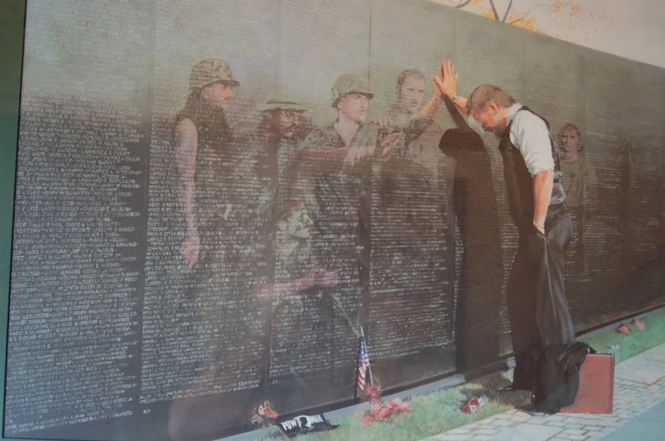
Looking for my first contact with the new station, using the Johnson Viking Valiant and the Hammarlund HQ 170 ! 160 meter AM contact you ask? Of Course !
New AM/CW/SSB Station

STATION OVERVIEW
Thge new station lives on a 6' operating desk which was part of my in shop area service bench. A new service bench was placed in service this past winter, (STUDIO G) making room for the current "boat anchor" station. The station is set up in three sections. The left side transmitter stack. The center receiver section. The right side receiver stack. Starting with the right side tranmitter stack, the bottom transmitter is a Johnson Vking Valiant. The transceiver above it is currently a Kenwood TS 820 with remote speaker. Above that is a Heathkit HM-102 watt meter, Electric Radio tuning meter, and a Heathkit SB 610 monitior scope.
The center section starting at the bottom houses a Rack Rider Power Conditioner, Model RR-15NL. The receiver above the Rack Rider is a restored Radio Shack Model DX-160, with matching speaker. The 19' panel above the DX-160, contorls antenna and audio feed for the DX-160 and the Drake 2C receiver / 2-CQ Q multiplier.
The right side receiver stack starting at the bottom, is a restored Hammarlund HQ 170 receiver. Above that is the Hallicrafter SX 110 and matching speaker. The receiver stack will also be getting a SX 71 receiver sometime later this summer.
The D104 microphone with a grip to talk stand services the Johnson Valiant, as does the Heathkit HD-1410 electronic keyer. The Turner 454C SSB microphone services the Kenwood TS 820 transceiver..
16 February, 2010

The Block Diagram is taken from the Flex Radio Opeating Manual 2007. The diagram shows the Personal Computer, interface cables, 1000D transceiver, to include additional accessories which can be added to the Flex Radio System.
The Diagram gives you a good overall view and understanding of the interconnections required. Note that the standard input and outputs on the Personal Computer are used, this makes interfacing the outputs from the 1000D compatible with the inputs of the PC. This holds true for the outputs on the PC being compatible with the inputs on the 1000D.
The Diagram also shows that there are alternate sources for audio output, one output on the PC, the other on the 1000D. The second source is a polled keyer paddle input, one on the PC, the other on the 1000D. This added some flexability when determining a location for 1000D hradward housing.
29 January, 2010
Power SDR Test & Measurement Area

I am very fortunate to have a special area with in the "shack" which is separate from the HF operating console, as well as the test bench area. This small area, is were I am able to setup and do some software testing and hardware interfacing and not tie up the test bench, or the operating console. However, the area in the photo is just behind my HF console and close enough to the test bench if needed!
As you can see, I use a three level oversize rack to do the hardware setup. The top shelf holds the 19" Envision monitor. The monitor has dual video (AVG, DMI) inputs. On either side of the monitor are the two stereo Inland, Pro sound 2000 series multi media amplified speaker system. The speakers are connected to the output of the PC which is fed by the Delta 44 audio interface from the 1000D. These speakers work very nicely, as they are small and produce a very good quality audio for initial setup and testing. In addition, to the right of the monitor is a standard PC wired mouse, as well as the Griffin knob. The Griffin knob allows the operator to tune the transceiver, as if it were a hardware tuning dial, as opposed to using the mouse to tune the transceiver.
The second shelf (center) holds the "hardware box" 1000D, which is not visible because of the keyboard drawer being extended. I have placed the 1000D out of the way, as there is no need to have it visible, as there are no controls on it, except the power switch. The Delta 44 audio interface is also at the rear of the shelf and out of the way. To the far right is the desktop Acer AXT mid tower. The configuration of the tower is as follows: (1)Processor-Athlon AMD 64- 3800(+) 2.4Ghz, with 2GB of Ram, running Windows XP Pro version 2002 and service pack 2. (2)Dual DVD drives. (3)Hard Drives- dual 250GB drives, primary drive running windows operating system, second drive running Linux operating system. (4)Audio card- M-Audio Delta 44 with external interface. (5)Video Card- dual channel video output with standard VGA and DMI outputs. (6)Dash Board- front panel, with several USB, and firewire ports. (7)Power Supply- 350Watt standard.
The third shelf (lower) provides space for the power supplies. The primary supply for the system is an Ashtron 35 Amp linear supply with metered outputs. The secondary supply used for other items not associated with the flex system, is a Pyramid Phase III Model PS-25, also with meters for voltage and current.
26 January, 2010
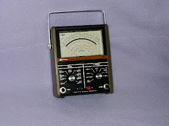
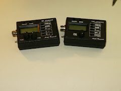
SDR 1000D Audio Interface to PC

Here is a closer look at the M-Audio interface or breakout box shown in the photo from the last post. M-Audio refers to this breakout box as their Delta series, which is this particular model.
As you can see there are 4 inputs and 4 outputs to the interface. Inputs 1 & 2 are line inputs. Inputs 3 & 4 are microphone inputs.
The outputs 1 & 2 are used to drive a pair of amplified speaker, as would be used for audio from your PC. Outputs 3 & 4 are the line outputs, which I referenced from the last post.
Flex-Radio use M-Audio as one of several "approved" audio interfaces along with an audio card which is installed in the PC. This particular M-Audio interface came with the 1000D when I purchased it, as both the Flex 1000D, and the accessory item were all pre-owned.
The audio interface does not come with any of the old or newer Flex systems, they must be purchased separately, along with the other items required for a complete operating system.
I currently use the speaker outputs to feed a pair of amplified Inland Pro Sound 2000 mulit-media speaker systems. They are moderately priced and have a very good sound quality for HF AM and SSB operation.
On the back side of the interface is the PC type "D" connector which connects to the rear panel of the PC.
Subscribe to:
Posts (Atom)

.JPG)


.JPG)

